Softwarebus - part 2: Diagnosis
A software bus is a communication channel via which several software modules can communicate without knowing each other. It encourages loose coupling of the modules and thus leads to a more understandable, reusable, testable and maintainable software. One advantage of the software bus is that it leads to easily readable code. A line like
IF NOT bEmergencyStop THEN
	GVL_Softwarebus.stWrite.stRelease.bMachineOn := FALSE;
END_IF
is immediately understandable. The machine reactions are programmed where they are triggered. Thus it is obvious to which machine reaction this line of code leads. However, it is not immediately obvious which other places in the code lead to the same reaction. In addition, a different structure is written (stWrite) than is read (stRead), which causes the cross-reference searches to be adjusted by hand. Thus the question which code leads to a certain reaction of the machine cannot be answered right away.
In the course of debugging, a frequently asked question is, for example:
Why can’t the machine be switched on?
If you know the places in the software that prevent the machine from switching on, this question can be answered easily. In this article we will look at how to make them visible.
The testbed
We build on the example of the first article, but this time we will represent the software bus in a different way. Furthermore, we will add a diagnostic option of the software bus to the visualization.
The goal
We want to create a diagnostic option for the PLC software in the HMI. It should be displayed
- which enable or action signals are active at the moment,
- in which block they are formed and
- a reason why they are active.
For this we will use a simple datagrid that we bind to a structure in the PLC that provides the needed information.

In addition to the message system, this diagnostic page provides a detailed overview of the machine status. In the event of an error, the programmer or the maintenance department is given a precise indication of where to look in the PLC software.
Based on the example from part 1, we will slightly modify the structure of the software bus to integrate the diagnostics. So far we have used a structure with boolean variables, which existed twice: in the stRead structure and in the stWrite structure. Action signals were initialized with FALSE, Release signals with TRUE. A simple read or write access was possible via these structures:
GVL_Softwarebus.stWrite.stRelease.bMachineOn := FALSE;   // write access
bDummy := GVL_Softwarebus.stRead.stRelease.bMachineOn;   // read access
Enum instead of struct
Instead of a structure we will use an enumeration, because it offers two advantages:
- the enumeration constant can be used as index of an array access (among other things the diagnostic data is stored in this array)
- via the
'to_string'attribute, theTO_STRINGoperator can be used to output the name of the enumeration component as a string instead of the enumeration value. Using this operator, we can generically write the triggered signal to the dignose table.
We create a structure for the Action software bus and the Release software bus respectively:
{attribute 'qualified_only'}
{attribute 'strict'}
{attribute 'to_string'}
TYPE E_SoftwarebusAction :
(
	Reset,
	Start,
	Stop
)UINT;
END_TYPE
{attribute 'qualified_only'}
{attribute 'strict'}
{attribute 'to_string'}
TYPE E_SoftwarebusRelease :
(
	MachineOn,
	MachineAutoOn
)UINT;
END_TYPE
If no explicit values are specified for the enumeration components, TwinCAT automatically assigns them ascending values starting from zero. In addition to the to_string attribute, the strict and qualified_only attributes were also specified. These are automatically inserted when an enumeration is created and it is recommended to keep them.
The signals of the software bus are now defined. However, an enumeration alone cannot set/reset boolean values. To achieve this, we create a block that does this for us: The FB_Softwarebus.
FB_Softwarebus
Until the software bus works, there is still some work left:
- A structure must be created in which the software bus “lives”, i.e. an
ARRAY [*] OF BOOL. - This is fourfold, for the Read- and the Write-part, which in turn are further subdivided into Action and Release.
- At the beginning of the PLC cycle the Write part is initialized: Action with
FALSEand Release withTRUE. For this we create the methodInitialize(). - At the end of the cycle we copy Write to Read. We call this method
Finalize(). - For diagnostics we create a structure with the elements Signal name, Path and Description, which is displayed in the HMI.
- We read the instance path of the
FB_Softwarebusand put it in the diagnostic structure. - Finally, we need a handful of helper functions to populate the datagrid in the HMI.
Generally it makes sense to have only one software bus in the machine. Therefore, static variables are used in the FB.
At first glance, the FB_Softwarebus resembles a Singleton, a design pattern of the Gang of Four. It describes an object of which there is exactly one instance project-wide. This is not possible under TwinCAT, because an FB is instantiated already at its declaration and thus another instance is automatically created via the declaration 1.
In addition, although we only want to access a software bus with the ‘FB_Softwarebus’, we certainly want to create several instances of the FB itself. The instance path of the FBs is read out and displayed in the HMI.
Local Softwarebus structures
First we create four arrays in the static variable area where the bits of the software bus can be written.
VAR_STAT
    // Softwarebus
	SoftwarebusActionRead	:	ARRAY[0..SOFTWAREBUS_ACTION_SIZE] OF BOOL;
	SoftwarebusActionWrite	:	ARRAY[0..SOFTWAREBUS_ACTION_SIZE] OF BOOL;
	SoftwarebusReleaseRead	:	ARRAY[0..SOFTWAREBUS_RELEASE_SIZE] OF BOOL;
	SoftwarebusReleaseWrite	:	ARRAY[0..SOFTWAREBUS_RELEASE_SIZE] OF BOOL;

    // Diagnosis
	...
END_VAR
VAR CONSTANT
	SOFTWAREBUS_ACTION_SIZE		: 	UINT := 3;
	SOFTWAREBUS_RELEASE_SIZE	: 	UINT := 2;
END_VAR
Fixed array sizes? With every extension of the software bus this declaration has to be updated, a clear violation of the Open-Closed principle! To overcome this pitfall, there are two possibilities:
- passing the array sizes to the FB and dynamic array building with the help of the
_newoperator. - declaration of the arrays in a global variable list. These arrays are then passed to the block via the
IN_OUTarea.
The first solution has the disadvantage that in addition to the software bus arrays, the arrays for diagnostics are also created dynamically. These however are bound to the datagrid in the HMI and a data binding to POINTER TO BYTE does not work.
The second solution would be the correct approach. However, it requires two things:
- The global variable list must be passed to each instance.
- This must be done before accessing the software bus via methods in this instance. With each access it must be checked with
_ISVALIDREFwhether overIN_OUTa valid reference was passed.
For this example I stay with the local static arrays with fixed sizes and consider it as one of the trade-offs I have to make as a PLC programmer compared to the world of modern programming languages.
The software bus is now set up and will have the old familiar structure in which the Read/Write bits can be initialized, set and written.
Diagnosis struct
To provide the three information signal name, path and description we create a suitable structure.
TYPE ST_HmiSoftwarebus :
STRUCT
	Signal    	 : STRING;
	Path	         : STRING;
	AdditionalText	 : STRING;
END_STRUCT
END_TYPE
From this type we now form four arrays:
diagnosisArrayReleaseanddiagnosisArrayAction: in these two arrays all signals are stored, regardless of whether the corresponding bit in the software bus is currently active.hmiArrayReleaseandhmiArrayRelease: in the HMI only the active signals shall be displayed. Therefore these two arrays contain a filtered set of the signals.
VAR_STAT
    // Softwarebus
	...

    // Diagnosis
	diagnosisArrayRelease : ARRAY[0..SOFTWAREBUS_RELEASE_SIZE] OF ST_HmiSoftwarebus;
	hmiArrayRelease : ARRAY[0..SOFTWAREBUS_RELEASE_SIZE] OF ST_HmiSoftwarebus;
	diagnosisArrayAction	 : ARRAY[0..SOFTWAREBUS_ACTION_SIZE] OF ST_HmiSoftwarebus;
	hmiArrayAction	 : ARRAY[0..SOFTWAREBUS_ACTION_SIZE] OF ST_HmiSoftwarebus;
END_VAR
Write access: SetAction() and SetRelease()
Having set up the basic structures, we can now operate on them.
Each time a signal is written in the software bus, a diagnostic entry is created, which indicates, at which place in the software and for what reason the signal was written. To achieve this we use two methods: SetAction() and SetRelease().
METHOD SetAction : BOOL
VAR_INPUT
	Signal		:	E_SoftwarebusAction;
	Text		:	STRING := '';
END_VAR

SoftwarebusActionWrite[Signal] := TRUE;
AddDiagnosisEntry(TO_STRING(Signal), Signal, Text, E_SoftwarebusType.Act);
First the corresponding bit is set in the software bus array. The enumeration component acts as an index. Furthermore, a diagnostic entry is created.
The enumeration component Signal is passed twice: once packed into the function TO_STRING(), which outputs the name of the component instead of the value and once as a value itself.
AddDiagnosisEntry()
This function populates the diagnosisArray with the corresponding data.
METHOD PRIVATE AddDiagnosisEntry : BOOL
VAR_INPUT
	EnumString		:	STRING;
	EnumValue		:	UINT;
	Text			:	STRING;
END_VAR
VAR_IN_OUT
	SwBusType		:	ARRAY[*] OF ST_HmiSoftwarebus;
END_VAR

SwBusType[EnumValue].AdditionalText := Text;
SwBusType[EnumValue].Path := GetShortenedPath();
SwBusType[EnumValue].Signal := EnumString;
Instance path
In the local area of the FB_Softwarebus we define a variable path that contains the instance path of this FB.
{attribute 'reflection'}
FUNCTION_BLOCK FB_Softwarebus
VAR
  {attribute 'instance-path'}
  {attribute 'noinit'}
  path	 :	STRING;
END_VAR
For this purpose the FB must be marked with the attribute pragma {attribute 'reflection'} on the one hand and the variable itself with the attributes {attribute 'instance-path'} and {attribute 'noinit'} on the other hand. The former ensures that the instance path is stored in this variable, the latter prevents the variable from being initialized as an empty string.
The method GetShortenedPath(), which is called in the method AddDiagnosisEntry, reads the instance path of this module and returns it shortened. Thereby the project name at the beginning of the instance path as well as the instance FB_Softwarebus at the end are hidden, because they are irrelevant.
Read access via GetAction() and GetRelease()
The GetAction() and GetRelease() methods return the status of the software bus.
METHOD GetAction : BOOL
VAR_INPUT
	Signal		:	E_SoftwarebusAction;
END_VAR

GetAction := SoftwarebusActionRead[Signal];
However, this also has a significant disadvantage when diagnosing the program: The return value of a function cannot be displayed in the online view.

Two additional properties provide convenience for read access
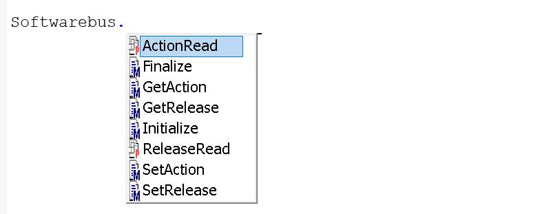
In order to circumvent this disadvantage, it is recommended to expose the Read part of the software bus via properties. We add the properties ActionRead and ReleaseRead, each of which has one getter and returns the corresponding software bus array.
PROPERTY ActionRead : ARRAY[0..SOFTWAREBUS_ACTION_SIZE] OF BOOL;
ActionRead := SoftwarebusActionRead;
This array can now be placed on an array located in a global variable table, for example.
GVL_Softwarebus.ActionRead := Softwarebus.ActionRead;
GVL_Softwarebus.ReleaseRead := Softwarebus.ReleaseRead;
Again the question arises, whether one does not pass the arrays from the GVL over the IN_OUT area to the FB_Softwarebus. But again I would not do it to keep the code as lean as possible.
Now the status of the signal in the software bus can also be observed in the online view:

In theory, there is a third possibility: read access to the internal array of the software bus in the FB_Softwarebus. TwinCAT allows read access from outside the block. However, it is not recommended because it contradicts the idea of data encapsulation. For this reason IntelliSense does not list the internal variables of a block as soon as it is accessed externally. Only methods and properties are listed.
Initialize() and Finalize()
Finally, the initialization of the software bus arrays and the copy from Write to Read remains, analogous to the basic software bus example from part 1.
// Initialize software bus
MEMSET(ADR(SoftwarebusActionWrite), 0, SIZEOF(SoftwarebusActionWrite));
MEMSET(ADR(SoftwarebusReleaseWrite), 1, SIZEOF(SoftwarebusReleaseWrite));

// Copy diagnostic data to display in HMI
FOR i:=0 TO SOFTWAREBUS_RELEASE_SIZE BY 1 DO
	ResetHmiArrayRow(hmiArrayRelease[i]);

	IF SoftwarebusReleaseRead[i] = FALSE THEN
		MEMCPY(ADR(hmiArrayRelease[hmiArrayIndex]), ADR(diagnosisArrayRelease[i]), SIZEOF(diagnosisArrayRelease[i]));
		hmiArrayIndex := hmiArrayIndex+1;
	ELSE
		ResetHmiArrayRow(diagnosisArrayRelease[i]);
	END_IF
END_FOR

hmiArrayIndex:=0;
FOR i:=0 TO SOFTWAREBUS_ACTION_SIZE BY 1 DO
	ResetHmiArrayRow(hmiArrayAction[i]);

	IF SoftwarebusActionRead[i] = TRUE THEN
		MEMCPY(ADR(hmiArrayAction[hmiArrayIndex]), ADR(diagnosisArrayAction[i]), SIZEOF(diagnosisArrayAction[i]));
		hmiArrayIndex := hmiArrayIndex+1;
	ELSE
		ResetHmiArrayRow(diagnosisArrayAction[i]);
	END_IF
END_FOR
In addition, the diagnostic data is evaluated: only the signals of the software bus that deviate from their initialization value are displayed in the HMI.
Putting everything together
Softwarebus.Initialize();
GVL_Softwarebus.ActionRead := Softwarebus.ActionRead;
GVL_Softwarebus.ReleaseRead := Softwarebus.ReleaseRead;

// ### Write examples ###
// ----------------------

// Action
IF bJogButton THEN
 Softwarebus.SetAction(Text:='Jog Button pressed.',
	Signal	:=	E_SoftwarebusAction.Start);
END_IF

IF bResetButton THEN
 Softwarebus.SetAction(Text:='Reset pressed.',
	Signal	:=	E_SoftwarebusAction.Reset);
END_IF

// Release
IF bEmergencyStop THEN
 Softwarebus.SetRelease(Text:='Emergency stop active.',
	Signal	:=	E_SoftwarebusRelease.MachineOn);
END_IF

IF bCriticalFault THEN
 Softwarebus.SetRelease(Text:='Critical fault active.',
	Signal	:=	E_SoftwarebusRelease.MachineOn);
END_IF

IF bCircuitBreakerTripped THEN
 Softwarebus.SetRelease(Text:='Circuit breaker has tripped.',
	Signal	:=	E_SoftwarebusRelease.MachineOn);
END_IF

IF bManualMode THEN
 Softwarebus.SetRelease(Text:='Manual mode active.',
	Signal	:=	E_SoftwarebusRelease.MachineAutoOn);
END_IF


// ### Read examples ###
// ---------------------

// read-access via getter
bResetLED := Softwarebus.GetAction(E_SoftwarebusAction.Reset);

// read-access via global variable list
bResetLED := GVL_Softwarebus.ActionRead[E_SoftwarebusAction.Reset];

Softwarebus.Finalize();
TwinCAT HMI
Let’s stay with Beckhoff for this example and add an HMI project to the PLC. To do this, we use the TwinCAT HMI. It is integrated into Visual Studio and enables modern user interfaces to be developed using HTML5 and JavaScript.
Since Siemens has caught up in TIA Version 16 with WinCC Unified, these web technologies will become the new standard for visualizations in the PLC world. The transition from proprietary solutions to these widely used technologies allows the use of countless existing libraries, which opens up a multitude of new possibilities at a stroke.
Set up
All active signals of the software bus Action and Release are to be displayed on the HMI. A simple datagrid is sufficient, the binding to hmiArrayRelease or hmiArrayAction should be switchable by two buttons.
In Desktop.view we create a Datagrid and two Buttons. To bind a Datagrid to a structure, the columns must contain the names of the variables in the structure.

Data binding
First I map in the TwinCAT HMI Configuration the two arrays from the FB_Softwarebus.

Now only the data binding of the datagrid to the respective array is missing. A short piece of code in the OnPressed event of the two buttons handles that:
var myControl = TcHmi.Controls.get('TcHmiDatagrid');
if(myControl){
    TcHmi.Binding.createEx('%s%PLC1.FB_Softwarebus.hmiArrayAction%/s%', 'setSrcData', myControl);
}
Here, the first button binds the Action array and the second binds the Release array.
Final remark
The simple setting and resetting of boolean variables has been replaced by a complex structure. Does the result justify the effort? In small projects: No. In medium sized projects it soon looks different: with every line of code the complexity of the software increases. Clarity of code becomes the main focus. More and more modules contribute to a global machine state. From this moment on, the software bus shows its strength. Machine reactions can be programmed locally, and they can easily be tracked via the diagnostic function. Once set up, this information is also available to maintenance, allowing deep insights into machine functionality.
In fact, this is just one reason of several. In his Thesis, Armando Rene Naravez Contreras investigates, among other things, the use of the Singleton pattern under CoDeSys. ↩︎